The story for this unit is much the same as when I got my DR-110, a nice sounding box but little way if interfacing it to MIDI.
It uses a PIC12F675 to create 4 clock pulses per metronome output from the 24 midi clocks per metronome input. The start and stop pins remain at a high impedance and go low impedance 0V for approximately 12mS on receiving the respective midi start or stop. This was done for easy interfacing.
As well as being able to sync the DR-55 to midi, with the flick of a switch,
the DR-55 can now sync to its own clock and will transmit 24 midi clocks per
metronome and midi start and stop according to the DR-55 internal clock and run
status. It generates the 24 midi clocks per metronome by transmitting 6
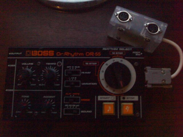
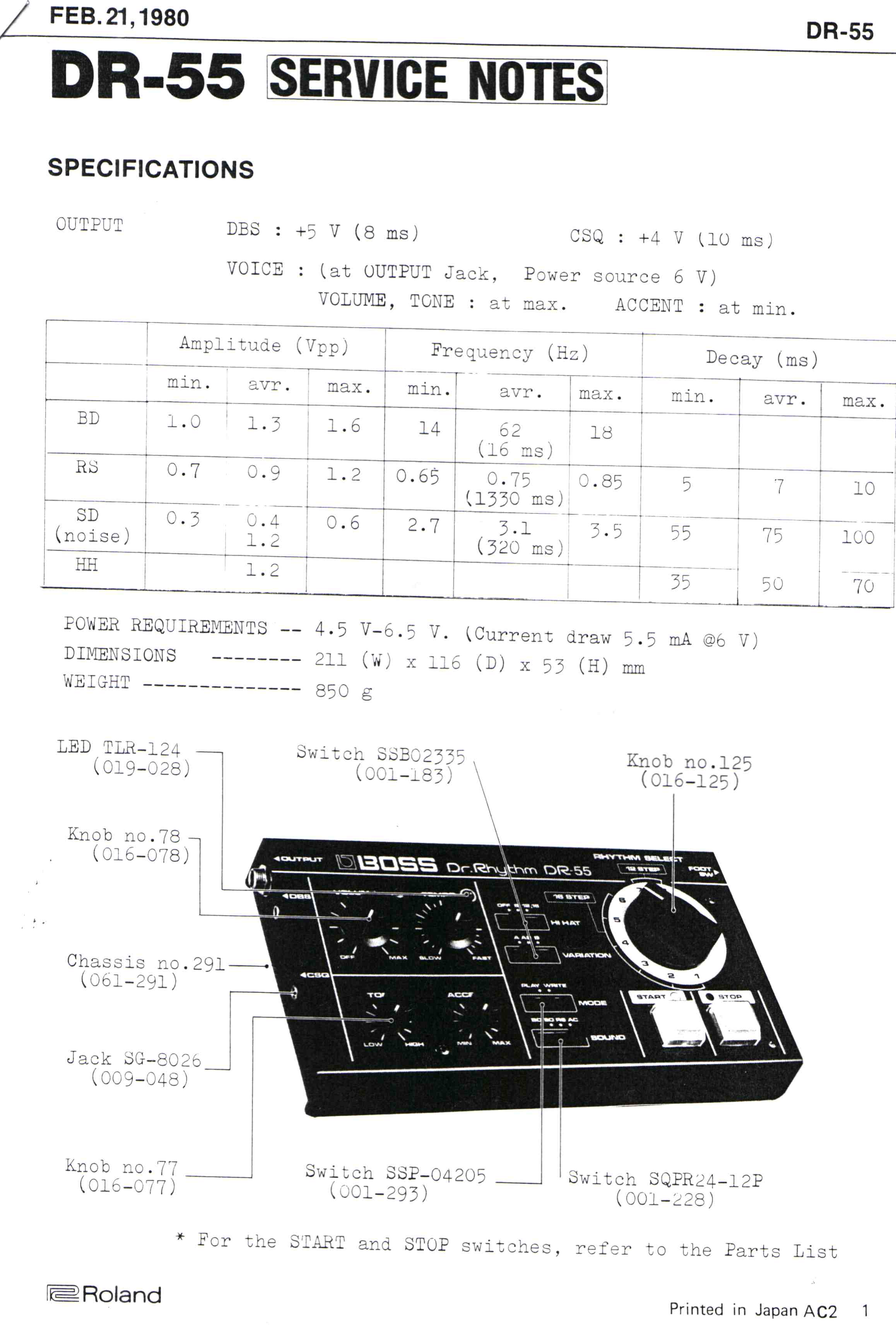
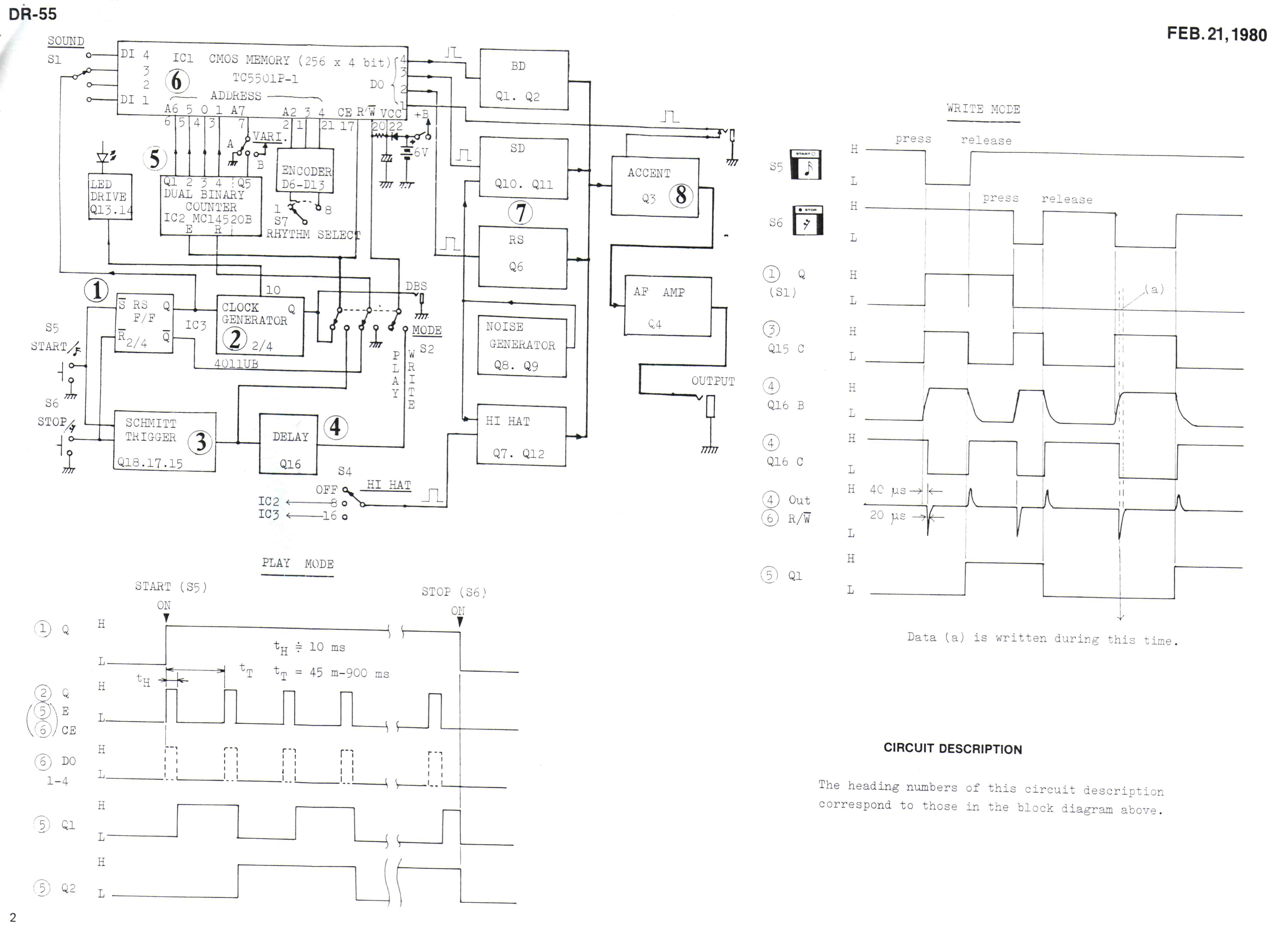
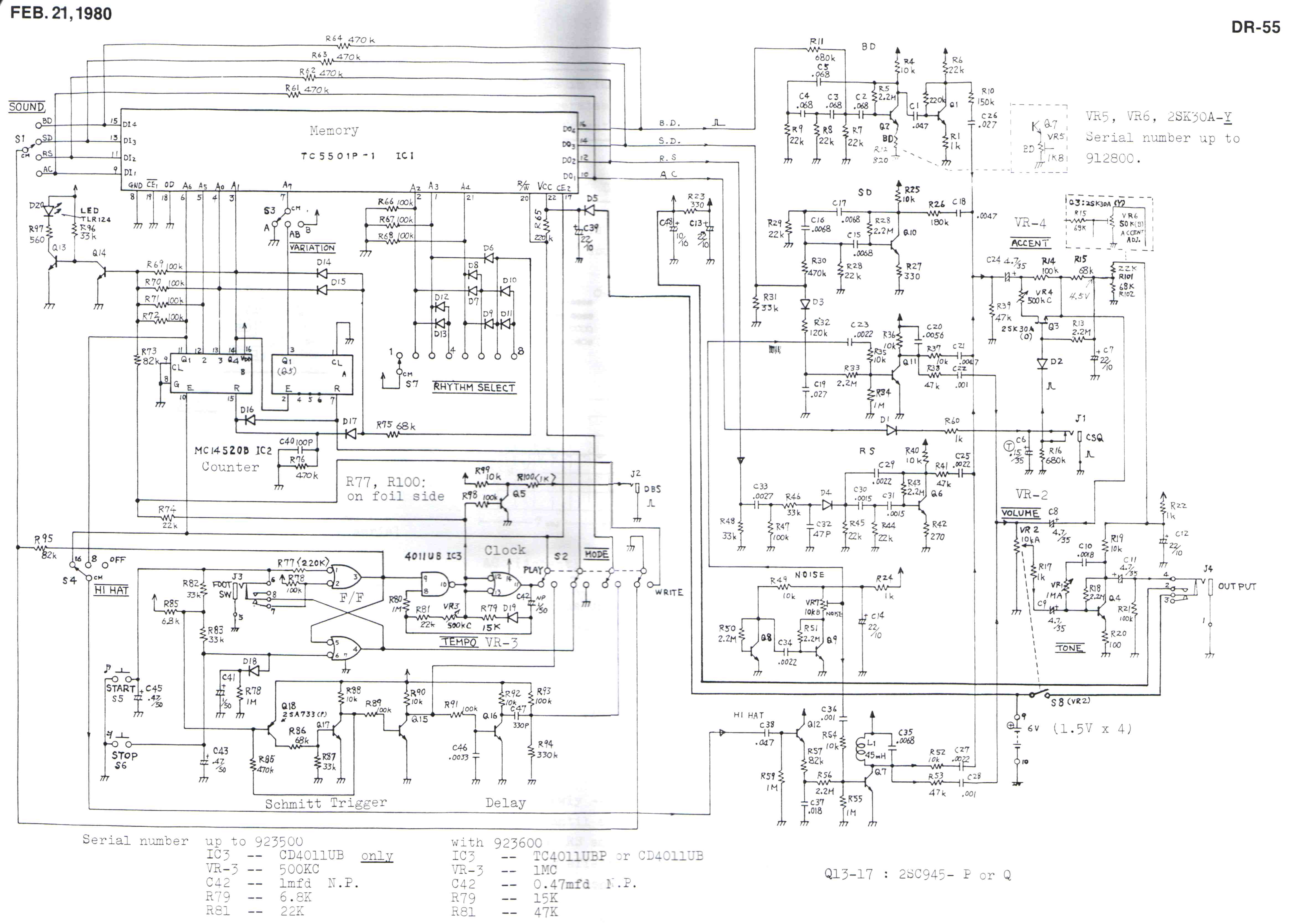
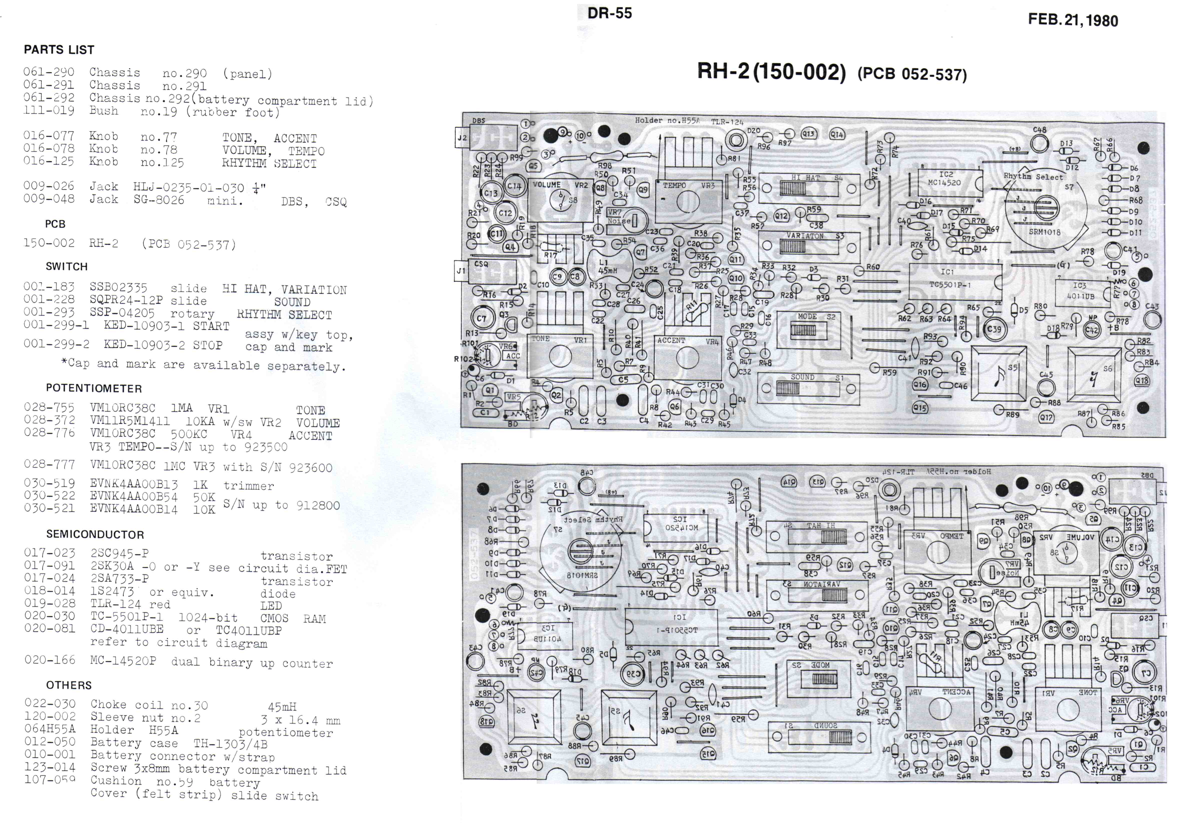
The circuit has 6 wires that need to be connected to the DR-55 internals. I powered the circuit from the internal power supply (2 wires), +V being after the power switch on the DR-55 board. A start and stop wire need to be wired to the DR-55 board (2 wires), they share the same holes as the start and stop buttons themselves. The final two wires are for the sync pulse. A jumper wire needs to removed and replaced with two wires. One wire being the DR-55 clock-out, the other being the DR-55 clock in, it’s the jumper is right between the start and stop buttons, so it’s not hard to find. The six wires run to a DB9 connector grafted into the side of the unit. You don't have to use a DB9 connector, that's just how I did it. I don’t have my digital camera anymore, so I can't share photos of how I did it (maybe later if I get hold of one), but if you get the service manual off Colin Fraser's' site (he is the man!), it's not too hard to trace the board.
Unfortunately, unlike the DR-110, the stop button of the DR-55 does not work as you would expect. Because the stop button on the DR-55 normally stops the internal clock as well, if the clock continues to run in stop mode, the first step of the sequence keeps firing. That might be fixed in code at a later date (I have an idea on how to do it), all depends on how much it pisses me off because in external MIDI sync mode, I never use the start and stop buttons on the DR-55 anyways. If I get hassled enough, I might fix it when I get the time. When the DR-55 is acting as a master sync, the start and stop work as expected.
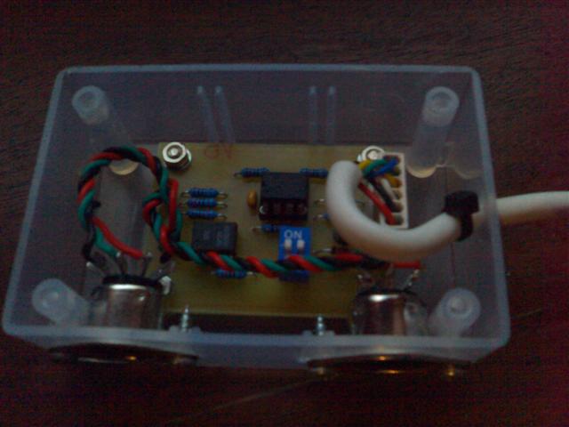
There was no room to put the new circuit and connectors inside the DR-55, I had to create an external circuit board.
The circuit is pretty strait forward. A 6N138 Opto-coupler is used for the MIDI input. R7 R8 and R9 limit the current on the output pins within the PIC spec. D1 is there to drop the supply voltage below 5.5V as required by the PIC specs. SW1 is a DPST switch (DPDT on the board) which acts to select the MIDI direction, and the DR-55 sync source.
| 12F675 Source Code - updated 10/4/2005. | |
| 12F629 Source Code - updated 16/12/2008. | |
| Schematic .PDF format | |
| Board layout .PDF format | |
| Component layout .PDF format |