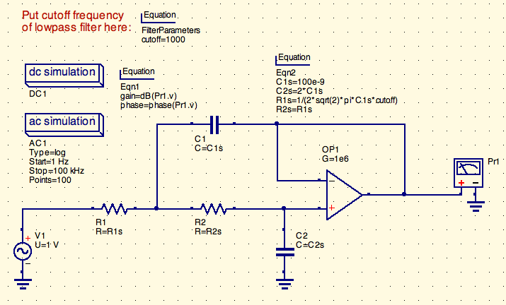
Qucs, short for Quite Universal Circuit Simulator, is as the name suggests a simulation package for electronic circuits. It's free and sports a nice graphical schematic capture interface. One of its many nice and useful features is the ability to write equations so you can calculate all kinds of stuff from simple linear equations up to Fourier transforms as part of the simulation. In this post I present a simple Qucs schematic for designing Sallen-Key Butterworth filters. It comes in three varieties: lowpass, highpass, and bandpass. Let's have a look at the lowpass version:

It#s fairly self-explanatory. You choose the desired cutoff
frequency of the filter and enter it as the variable cutoff in an
equation. The component values are then calculated using the standard
equations. Note, that the capacitor's values are fixed to 100nF and
200nF respectively. This is necessary because otherwise the system of
equations would not have a unique solution.
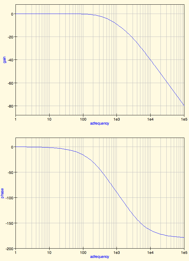
Once you simulate your design you are presented with a Bode plot, i.e. frequency and phase response of the filter.

Now, if you want to play around with it, get the Qucs project files.